Examples of creating load balancers
Video instruction available at bottom of page
HTTP load balancer
In this example, we will create a simple HTTP-type load balancer that will redirect HTTP traffic (port 80) from the vIP load balancer to the IP addresses of two instances created in the same project using the Round-Robin algorithm.
Currently, a network project-net-1 is created in the project along with a subnet project-subnet-1 with address 10.10.0.0/24. This network has Internet access via a router in the same project. In addition, 2 instances of backend-1 (10.10.0.106) backend-2 (10.10.0.195) have been created, having web servers listening on port 80, which return information with the name of the host to which the request comes.
STEP 1 - Creating a load balancer
In the first step, we go to the Project -> Network > Load Balancers tab where we click on the “+ CREATE LOAD BALANCER” button, which will start the load balancer creation wizard.
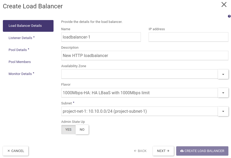
We set name, description, select flavour and subnetwork, where a vIP address will be created on which the load balancer will listen (this address can be from a private class, we will include a floating IP address from the public network in a later step). Leave the IP address and Availability Zones fields blank.
STEP 2 - Creating a listener
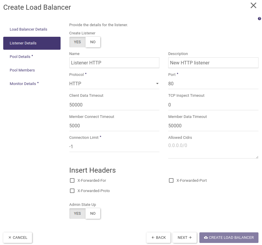
In the next step, we create a listener, i.e. define a protocol and a port on which our load balancer will listen for incoming calls.
We fill in name, description, select protocol (HTTP), port (80). The remaining fields are left filled in by default. These allow you to customise the basic properties of the load balancer with the HTTP listener and possibly add popular headers used in load balancing.
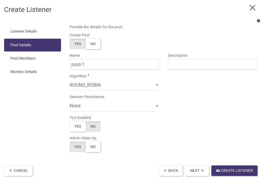
STEP 3 - Create a pool and select a load balancing algorithm
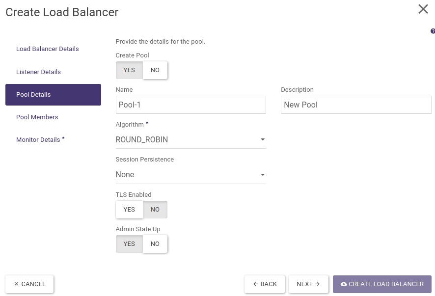
In the next step, we create a pool in which we will place the backends that handle the requests sent to the load balancer. We fill in name, description and select algorithm (ROUND_ROBIN). We leave the remaining fields default.
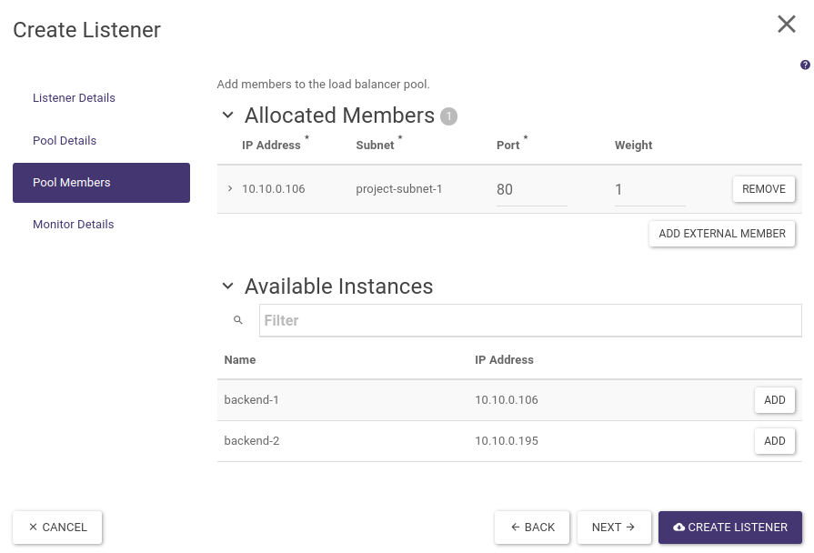
STEP 4 - Adding backends to the pool
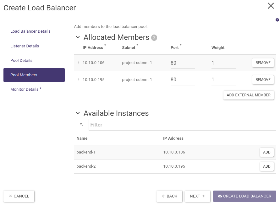
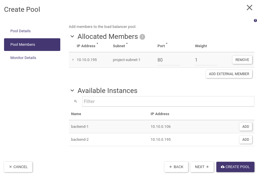
In the next step, we add backends (members) to the pool we created earlier.
Next to the available instances, we click on the ADD button. We fill in the ports on which our HTTP servers are listening (80). We leave the weights at the default, which will allow connections to be forwarded evenly to both servers.
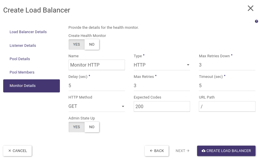
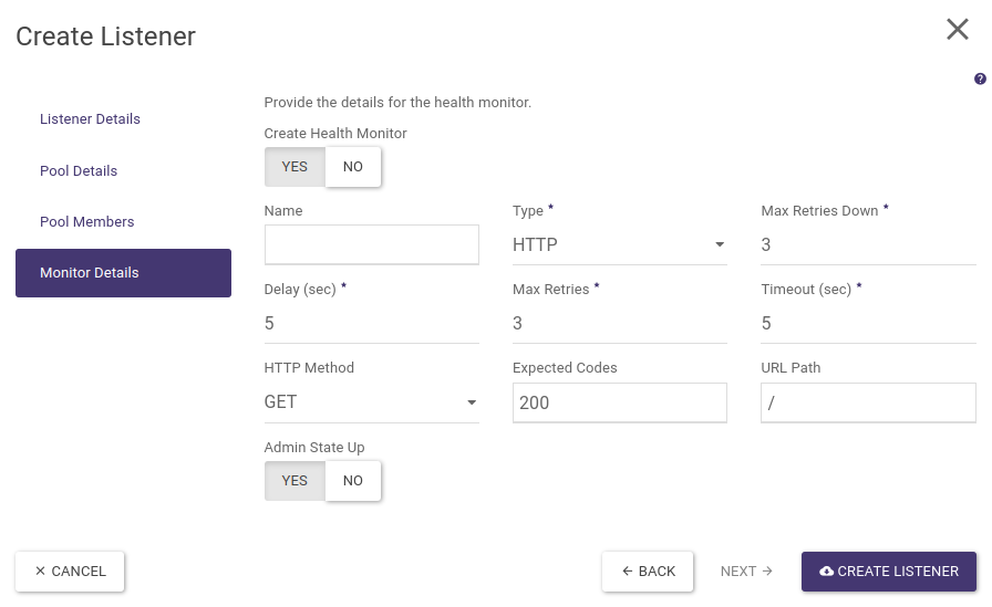
STEP 5 - Configuring the Health Monitor
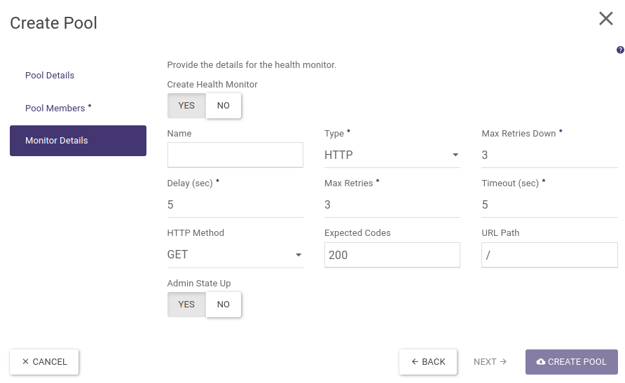
In the last step of the wizard, we configure how to monitor the availability of backends in the pool.
In our example, the monitoring will consist of periodically (5 seconds) querying the backend on the HTTP port (80) and checking if we receive a valid response (HTTP code 200). We will set name, HTTP type and leave the other fields default.
Finally, we confirm the creation of the load balancer by clicking on the button “CREATE LOAD BALANCER”. The load balancer creation process lasts from a few seconds to about 3 minutes (depending on the selected load balancer type - flavour).
When the load balancer is ready its parameters: Operating Status should be set as Online and Provisioning Status as Active.
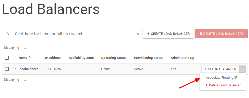
Finally, in order to make our load balancer accessible from the public Internet, we assign it a floating IP address. To do this, in the load balancer list, click on the options arrow and select Associate Floating IP.
In a further menu, we select the floating IP address assigned to our project or the pool from which we will assign a new IP address (EXTERNAL).
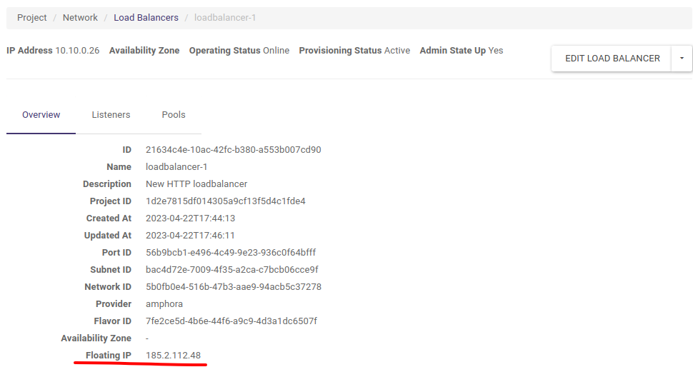
Once the floating IP address has been assigned, it will be visible in the load balancer properties available by clicking on its name.
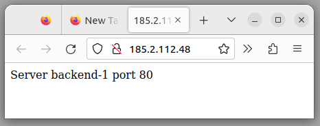
At this point, our load balancer is created and we can test its operation.
We enter the address of the floating IP load balancer into the address bar of the browser. Of course, we must ensure that the backends have the correct Security Groups settings accepting HTTP traffic (TCP/80 port).
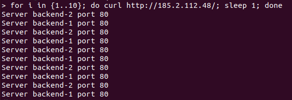
To illustrate the Round-Robin algorithm, we will run a simple loop querying our load balancer using the curl tool from the command line:
To create a similar load balancer using the OpenStack CLI we issue the following commands:
openstack loadbalancer create --name loadbalancer-1 --vip-subnet-id project-subnet-1 --flavor 1000Mbps-HA
Let’s wait for the load balancer to be created until the next command indicates operating_status ONLINE and provisioning_status ACTIVE
openstack loadbalancer show loadbalancer-1
openstack loadbalancer listener create --name listener-http --protocol HTTP --protocol-port 80 loadbalancer-1
openstack loadbalancer pool create --name pool-1 --lb-algorithm ROUND_ROBIN --listener listener-http --protocol HTTP
openstack loadbalancer member create --subnet-id project-subnet-1 --address 10.10.0.106 --protocol-port 80 pool-1
openstack loadbalancer member create --subnet-id project-subnet-1 --address 10.10.0.195 --protocol-port 80 pool-1
openstack loadbalancer healthmonitor create --name monitor-http --delay 5 --max-retries 3 --max-retries-down 3 --timeout 5 --type HTTP pool-1
We retrieve the ID of the vIP port from the load balancer properties and add the floating IP address previously allocated to our project
openstack floating ip set --port cf50d069-0e43-40ec-ae3e-e16119b9aae0 185.2.112.48
Loadbalancer HTTPS_TERMINATED
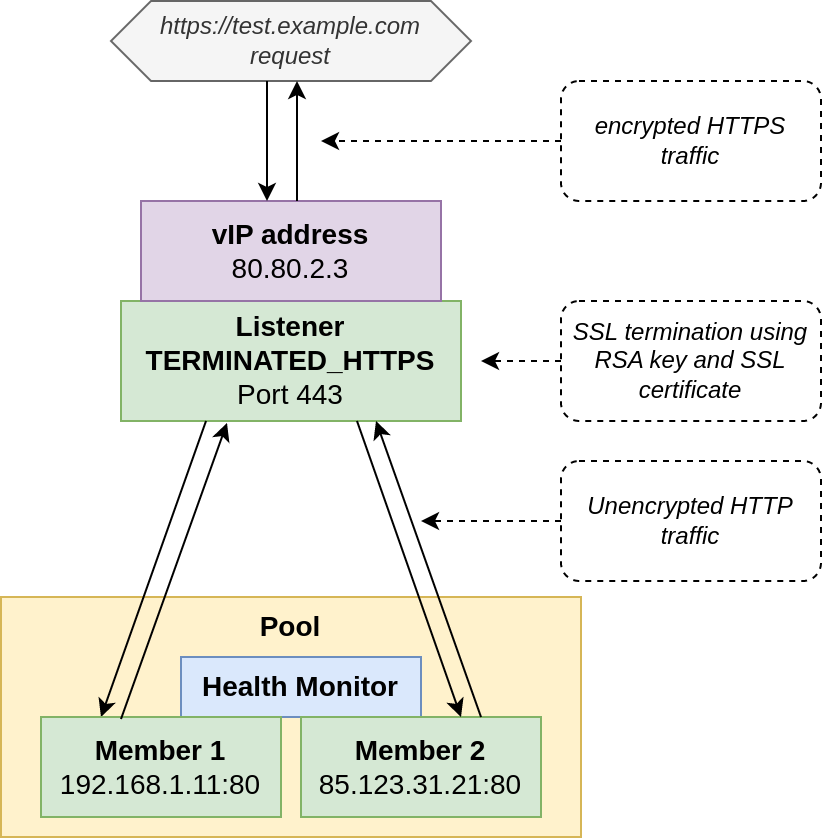
The next example describes the creation of a load balancer, which receives HTTPS requests, then using a private key and an SSL certificate sends encrypted traffic between the load balancer and the client (browser). The load balancer in the internal virtual network communicates with the backends using the usual HTTP protocol (unencrypted traffic).
The architecture of such a solution is shown in the diagram below:
Before we can start preparing the load balancer, we first have to upload the private key and the SSL certificate generated from it, and then create a so-called bundle from this pair. In Atman Cloud, this is only possible via the CLI/API.
In this example, we will use the packages python-openstackclient and python-barbicanclient (responsible for communication with the so-called secret store) installed on a Linux system using the PIP tool. In the example we will also generate self-signed certificates for the example domain test.example.com.
Generation of RSA key of size 3072 bytes (not password protected)
openssl genrsa -out test.example.com.pem 3072
Convert key from pem format to pkcs8 format acceptable to secret store
openssl pkcs8 -topk8 -in test.example.com.pem -out text.example.com.pk8 -nocrypt
Sending key to secret store in Atman Cloud, from the result of the command we save for later Secret href starting with http://controller is an internal identifier similar to a standard URL
openstack secret store --secret-type private --name test.example.com_key --file test.example.com.pk8
Generate SSL certificate using previously generated private key (DN field must match the requested domain)
openssl req -new -x509 -days 365 -key test.example.com.pk8 -out cert-test.example.com.pem
Send certificate to secret store in Atman Cloud, here also from the result of the command we save the secret href identifier for later
openstack secret store --secret-type certificate --name 'test.example.com_cert' --file cert-test.example.com.pem
Finally, using the previously saved key and certificate references, we create a so-called bundle, implemented in the Atman Cloud as a “secret container”, which we select when creating the load balancer using the name parameter in the Atman Cloud panel
openstack secret container create --type certificate --name cert-key-bundle-test.example.com --secret "certificate=http://controller.c2a.eco.atman.pl:9311/v1/secrets/d69361e6-b626-4867-b2c0-8d7f7f2bc970" --secret "private_key=http://controller.c2a.eco.atman.pl:9311/v1/secrets/cf07644c-17b9-4859-95eb-e3482670cb45"
We then proceed to the creation of the load balancer in the Atman Cloud web panel. In the following example, we will refer to the differences of creating a terminated HTTPS load balancer and the previously referenced HTTP load balancer.
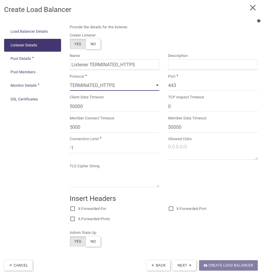
Point 1. regarding the creation of the load balancer itself is identical, while in point 2. in the Protocol field we select TERMINATED_HTTPS:
Then, identical to the HTTP load balancer, we create a pool, add backends to it and create a health monitor.
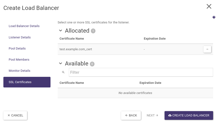
The last step will be to indicate the SSL certificate for our listener. After selecting “SSL Certificates” from the left-hand menu, click on the (+) sign next to the name of the previously created bundle and finally click CREATE LOAD BALANCER.
Once the load balancer has been created, as in the previous example, we assign it a floating IP address.
When the Operating Status of the load balancer changes to Online and Provisioning Status to ACTIVE, our backends will be accessible via HTTPS (port TCP/443), e.g. https://test.example.com. Note that in this example the SSL certificate is self-signed, hence the browser will return an untrusted certificate error.
The following commands can also be executed via the OpenStack CLI to create a sample loadbalancer with a terminated SSL connection (the creation and transfer of certificates described above are omitted):
openstack loadbalancer create --name loadbalancer-1-terminated-https --vip-subnet-id project-subnet-1 --flavor 1000Mbps-HA
Let’s wait for the load balancer to be created until the next command indicates operating_status ONLINE and provisioning_status ACTIVE
openstack loadbalancer show loadbalancer-1-terminated-https
When creating the listener, we provide the href identifier of the container with the certificate and private key that we previously created in the secret store, the container links can be displayed using the command “openstack secret container list”
openstack loadbalancer listener create --name listener-terminated-https --protocol TERMINATED_HTTPS --protocol-port 443 --default-tls-container-ref http://controller.c2a.eco.atman.pl:9311/v1/containers/a8119383-afce-4cd8-aec9-767e30ae5189 loadbalancer-1-terminated-https
openstack loadbalancer pool create --name pool-1 --lb-algorithm ROUND_ROBIN --listener listener-terminated-https --protocol HTTP
openstack loadbalancer member create --subnet-id project-subnet-1 --address 10.10.0.106 --protocol-port 80 pool-1
openstack loadbalancer member create --subnet-id project-subnet-1 --address 10.10.0.195 --protocol-port 80 pool-1
openstack loadbalancer healthmonitor create --name monitor-http --delay 5 --max-retries 3 --max-retries-down 3 --timeout 5 --type HTTP pool-1
We find the vIP port ID from the load balancer properties and assign the floating IP address previously allocated to our project
openstack floating ip set --port cf50d069-0e43-40ec-ae3e-e16158b9aae0 185.2.112.48
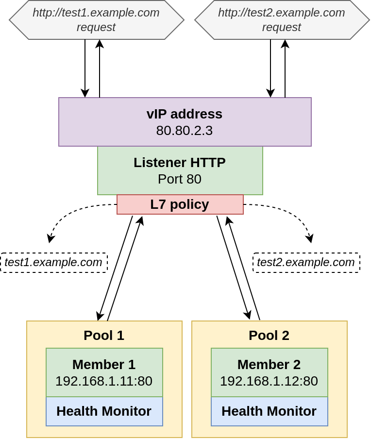
HTTP load balancer with layer 7 rules (L7 load balancing)
As an example of a load balancer using layer 7 rules, we will create one load balancer, having a single listener listening on port 80 and two server pools, with one backend in each. The pool will be selected based on the name of the host (corresponding HTTP header) we will be referring to.
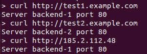
In our case, the host test1.example.com will forward traffic to the first pool and thus the server backend-1 and traffic to test2.example.com will be forwarded to the second pool and the server backend-2. The architecture we will create is shown in the diagram below:
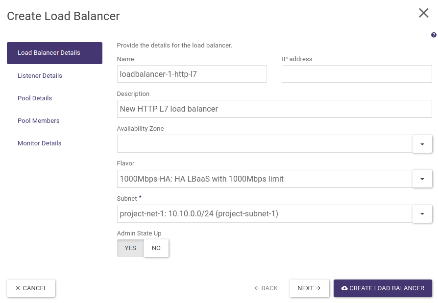
STEP 1 - Creating a load balancer
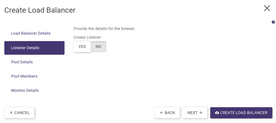
The load balancer creation wizard (launched by clicking on CREATE LOAD BALANCER) allows only one default pool to be created for the listener. Hence, we initially create the load balancer itself. In the Load Balancer Details step we fill in all relevant data and in the Listener Details step we set the Create Listener option to NO, we finish the wizard by selecting the CREATE LOAD BALANCER button.
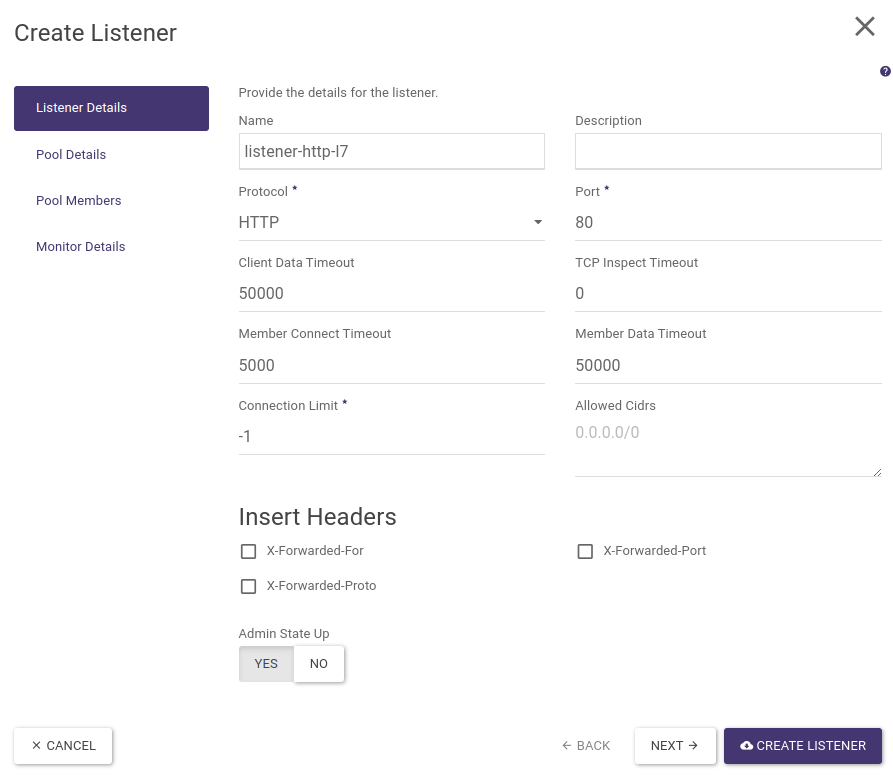
STEP 2 - Creating a listener and a default pool
The next step is to create an HTTPS-type listener and default pool to which all requests received by the listener will be passed. To do this, click on the name of the load balancer you created earlier, then go to the Listeners tab and select + CREATE LISTENER. At this point, a wizard for creating a listener will appear, which we complete in a similar way to the first example of a normal HTTP load balancer (without layer 7 policies). Remember to include only the backend-1 server in the first pool. The whole thing is shown in the screenshots below:
Finally, we select CREATE LISTENER.
STEP 3 - Creating a second pool and assigning a backend-2 server
The next step is to create a second pool and add a backend-2 server to it. To do this, go to the Pools tab in the load balancer settings (where the first pool should already be) and select + CREATE POOL. A wizard for creating a new pool will appear, complete all the steps as before, remembering to add only the backend-2 server:
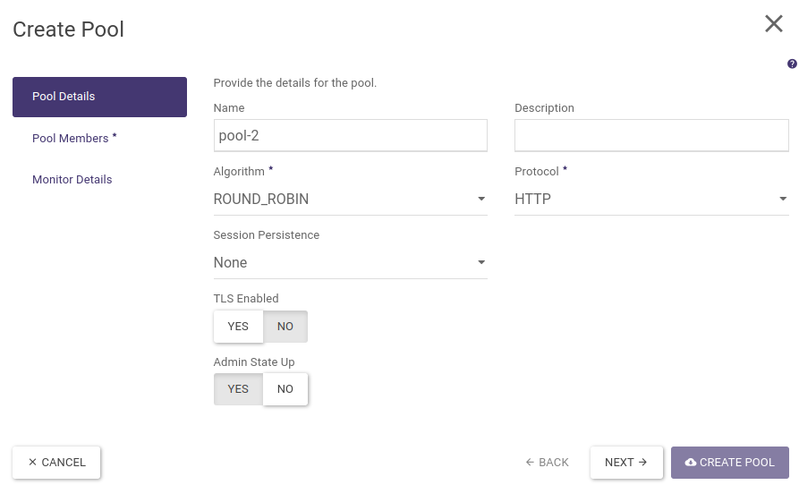
Confirm the wizard by selecting CREATE POOL.
STEP 4 - Creating Layer 7 policies and rules
In the current example, all traffic is still redirected to the pool-1 pool, due to the fact that it was created as the default pool for the listener (created when the listener was created). Hence, the next step is to create rules to redirect traffic to the backend-1 server for requests to the load balancer having the hostname test1.example.com in the header and to the backend-2 server for the hostname at test2.example.com. The first rule is of course redundant (due to the default role of pool-1), although created for readability of the configuration.
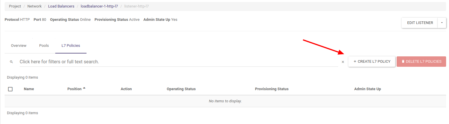
In the load balancer settings (accessible by clicking on its name), we go to the Listeners tab and click on listener name to access its settings. We then go to the L7 Policies tab and select + CREATE L7 POLICY, as in the screenshot below:
We then complete the policy name, select the REDIRECT_TO_POOL action and select the first pool (the pool name is shown by its UUID in brackets).
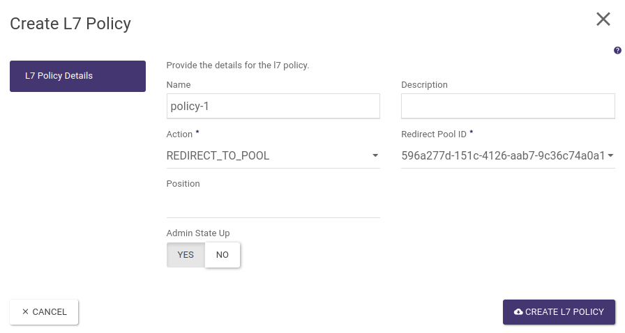
Validate the configuration by selecting CREATE L7 POLICY.
To create a rule for a policy click on the pool name, then go to the L7 Rules tab and click on + CREATE L7 RULE as shown in the screenshot below
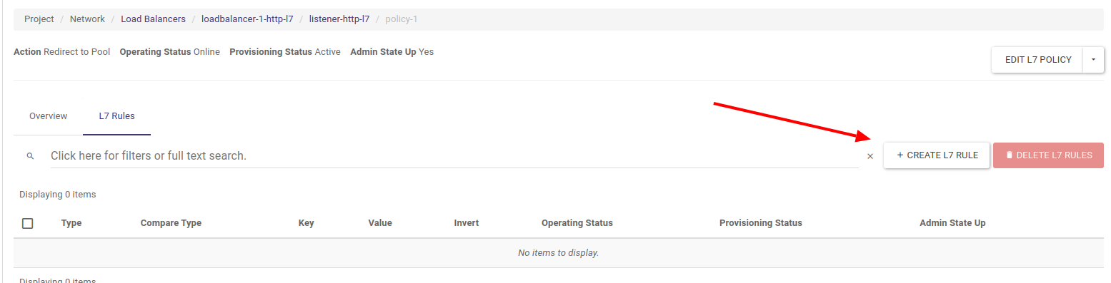
In the L7 rules configuration window, we select Type - HOST_NAME, Compare Type - EQUAL_TO and Value - test1.example.com

We then validate the configuration by clicking on CREATE L7 RULE.
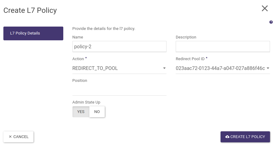
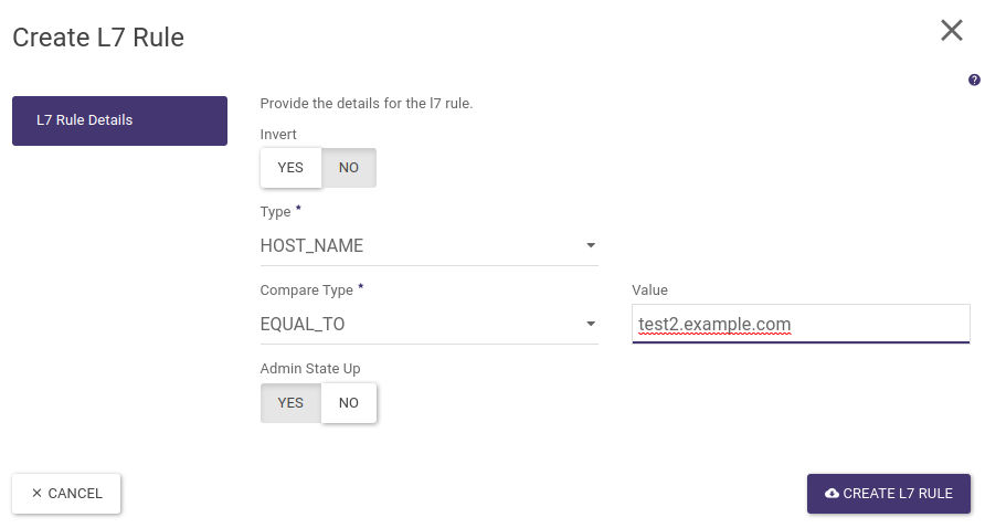
The next step is to create a policy and layer 7 rule for the hostname test2.example.com and redirect such traffic to the second pool. To do this, as before, go to the load balancer settings then in the Listeners tab click on the listener name and in the L7 Policies tab create a new L7 policy to redirect to the pool-2:
Once approved, click on its name, go to the L7 Rules tab and create a new rule:
STEP 5 - Assigning Floating IP address
The final step is to assign the Floating IP address, to the load balancer. In the load balancer list, expand the action menu and select Associate Floating IP
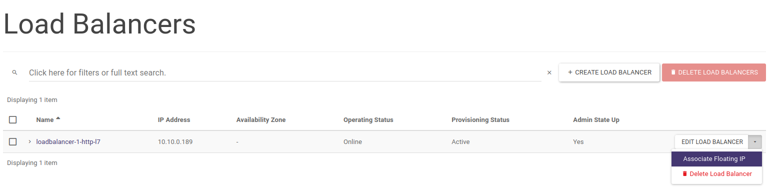
The desired public address is then selected and the action approved.
At this point our load balancer is ready and its operation with the Curl tool is shown below (please note that by default the redirection is set to the backend-1 server):
We can also create the above configuration using the OpenStack CLI:
First, we create a load balancer in the same way as for LB HTTP
openstack loadbalancer create --name loadbalancer-1-http-l7 --vip-subnet-id project-subnet-1 --flavor 1000Mbps-HA
We wait for the load balancer to be created until the next command indicates operating_status ONLINE and provisioning_status ACTIVE
openstack loadbalancer show loadbalancer-1-http-l7
We then create a listener of type HTTP on port 80
openstack loadbalancer listener create --name listener-http-l7 --protocol HTTP --protocol-port 80 loadbalancer-1-http-l7
We are creating two pools in which to place our backends, note that the first pool is assigned to the listener (it is also the default pool), hence all requests will go to it, even those that do not meet any conditions (e.g. direct access via IP address in the host field).
openstack loadbalancer pool create --name pool-1 --lb-algorithm ROUND_ROBIN --listener listener-http-l7 --protocol HTTP
openstack loadbalancer pool create --name pool-2 --lb-algorithm ROUND_ROBIN --loadbalancer loadbalancer-1-http-l7 --protocol HTTP
We then create a policy and rule to redirect queries with the hostname test1.example.com to the first pool (as noted above this policy is optional as the first pool is the default pool).
openstack loadbalancer l7policy create --action REDIRECT_TO_POOL --redirect-pool pool-1 --name policy-1 listener-http-l7
openstack loadbalancer l7rule create --compare-type EQUAL_TO --type HOST_NAME --value test1.example.com policy-1
We then create a second policy and rule to redirect queries with the hostname test2.example.com to the second pool
openstack loadbalancer l7policy create --action REDIRECT_TO_POOL --redirect-pool pool-2 --name policy-2 listener-http-l7
openstack loadbalancer l7rule create --compare-type EQUAL_TO --type HOST_NAME --value test2.example.com policy-2
We then add the individual backends to separate pools
openstack loadbalancer member create --subnet-id project-subnet-1 --address 10.10.0.106 --protocol-port 80 pool-1
openstack loadbalancer member create --subnet-id project-subnet-1 --address 10.10.0.195 --protocol-port 80 pool-2
The next step is to create health monitors for both pools (optional step)
openstack loadbalancer healthmonitor create --name monitor-http --delay 5 --max-retries 3 --max-retries-down 3 --timeout 5 --type HTTP pool-1
openstack loadbalancer healthmonitor create --name monitor-http --delay 5 --max-retries 3 --max-retries-down 3 --timeout 5 --type HTTP pool-2
Finally, we find the vIP port ID from the load balancer properties and assign the floating IP address previously allocated to our project
openstack floating ip set --port cf50d069-0e43-40ec-ae3e-e16119b9aae0 185.2.112.48
Provision of endpoint metrics in Prometheus format
In order to make the load balancer metrics available in a format parsable by the Prometheus system, a new listener must be added to the current load balancer to issue aggregate metrics. Currently, the addition of such a listener is only possible via the API or the CLI client together with the corresponding plugin.
To install the client together with the plug-in, run the command (example for Ubuntu, although for other systems or installation via PIP the package name will be similar):
sudo apt install python3-octaviaclient
Then, assuming you are running such a listener (Prometheus exporter for the Octavia module in OpenStack) on port 9885, which for loadablancer lb-1 will only issue metrics for clients (Prometheus servers that download metrics) connecting from a specific IP address, issue the command:
openstack loadbalancer listener create --name prometheus_exporter --protocol PROMETHEUS --protocol-port 9385 --wait --allowed-cidr 123.123.123.123/32 lb-1
From now on, metrics from the load balancer within which the above listener was created will be available on port 9385.
Note: Any time the aforementioned listener changes, the metrics will be reset to zero.
Video instructions